Wireless Communication
Basics
John Weber
webe9881@cslab.engr.ccny.cuny.edu
http://www-cs.engr.ccny.cuny.edu/~webe9881/


Waves

Wavelength
The time required for a signal to be transmitted over a distance of one wavelength (e.g. one sin wavelength is the value of the x-axis at sin(360DEG)). The wavelength of a signal has a significant impact on the size of the antenna required; The longer the wavelength, the larger the antenna. (NOTE: At low frequencies, the wavelength becomes quite long so it is equally correct to say that frequencies are also related to the size of the antenna).

Frequency
Frequency is the term used to refer to the number of waves that occur per second -- measured in hertz. The example here has a frequency of 1 Hz (i.e. 1 entire wavelength occurs per second).

Amplitude
The amount of energy carried by a wave is related to the amplitude of the wave. The amount of energy carried by a wave is related to the amplitude of the wave; the higher the amplitude the greater the energy in the wave.

Propagation
The loss in strength of a signal as it traverses a medium is referred to as propagation loss. Propagation loss increases with respect to both distance and frequency.

Propagation Loss and Distance As a signal propagates, it encounters some type of resistance (e.g. air molecules). Thus the further a signal travels, the weaker it becomes.

Propagation Loss and Frequency High-frequency components of a signal attenuate more rapidly. Thus propagation losses increase as the frequency used by a system increases (ceteris paribus).

Noise
In all communications systems there is a degree of noise, caused by the movement of electrons, power-line induction, and the cross-modulation from adjacent wire pairs or in wireless communications from frequencies in adjacent channels. There are two basic types of noise:

Thermal Noise (aka White or Gaussian Noise), such as the movement of electrons or basic radiation from the sun, is characterized by a near-uniform distribution of energy over the frequency spectrum. Therefore, it represents the lower level of sensitivity of a receiver because a received signal must exceed the level of background noise if it is to be discriminated from the noise by the receiver.

Impulse Noise, such as solar flares or lightning, is characterized by irregular spikes or pulses of energy of relatively high amplitude and short duration.

Communications Basics

Transmitters
To create a simple radio transmitter, what you want to do is create a rapidly changing electric current in a wire. The change in current in the wire will create a magnetic field. Using capacitors and inductors, this electromagnetic wave can be amplified.

Receivers
The two most important parts of the receiver are the antenna and the tuner. An antenna is simply a wire or a metal stick that increases the amount of metal the transmitter's waves can interact with. The antenna will receive thousands of sine waves. The job of a tuner is to separate one sine wave from the thousands of radio signals that the antenna receives. Tuners work using a principle called resonance. That is, tuners resonate at, and amplify, one particular frequency and ignore all the other frequencies in the air. Again, one can create a resonator with a capacitor and an inductor.

Modulation
In a wired network, data and voice are sent along the physical wire by mapping the information into voltages; low voltage is a binary 0 and high voltage is a binary 1. In order to send data or voice over a wireless network (a communications systems based on the transmission and reception of electromagnetic waves), the information must be mapped into the sine waves. Information can be mapped onto the wave by simply varying one of wave's characteristics and mapping those values to whatever data you wish to represent. For example, you could alter the frequency of the wave and map each frequency within the channel range to each one of the 26 characters in our alphabet. The altering of the wave's characteristics and the result of this process is referred to as modulation. Common modulation techniques include altering the amplitude of the carrier (amplitude modulation), altering the frequency of the carrier (frequency modulation), and altering the time period or phase of the carrier (phase modulation).

Bandwidth
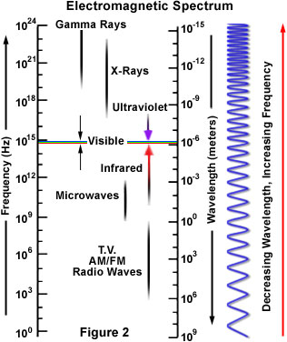
The frequency spectrum ranges from 1Hz to at least 10^23 Hz (as of the year 2001). Bandwidth refers to the portion of the frequency spectrum allocated for a given service; it is a measure of the width of a range of frequencies and not the frequencies themselves. While many wireless applications publicize that they operate at a precise frequency, actually that frequency is the center frequency around which voice/data is modulated and can change as a subscriber travels from one cell to another. The range of allowable frequencies then represents the bandwidth supported by the particular application.

The higher the frequency range, the higher the bandwidth (since a range from 10^12 to 10^15 is a lot larger, for example, than a range from 10^1 to 10

Note that fiberoptic communications are relatively high on the frequency portion of the chart (as it operates in the visible light spectrum), therefore the range of frequencies (or bandwidth) is very high. Because transmission rate is proportional to the bandwidth, this allows one fiber to replace thousands of copper cables.

Transmission Rate (Bits vs. Baud)
The bit rate (bps) represents a measurement of data throughput. In comparison, baud represents the rate of signal change, commonly expressed in terms of hertz. When information in the form of bits is to be transmitted, an oscillating wave is referred to as a carried.

For example, let's assume that binary 1's are modulated at frequency f1 and binary 0's are modulated at frequency f2. This modulation scheme would then allow each possible combination of two bits to be encoded into one signal change. So, in this case, the bit rate is twice the signalling rate.

NOTE: Modulation and transmission rate are related. The modulation scheme may allow each signal change to encode more and more bits and thus increase the bit rate.

Transmission Rate Constraints

The Nyquist Relationship states that the maximum rate at which data can be tramsmitted prior to one symbol interfering with another (intersymbol interference) must be less than or equal to twice the bandwidth in hertz. Because most transmission systems modulate or vary a signal, the Nyquist relationship puts a cap on the signaling rate that is proportional to the bandwidth. Thus, to transmit more data, the modem designer must pack more bits into each signal change.

B = 2W, where B is the baud rate and W is the bandwidth.

Shannon's Law then puts a limit on bit rate (by relating it to the noise on the line and the available bandwidth).

C = W lg(1+ S/N), where S/N is the signal-noise ration and W is bandwidth.

Overview of Wireless Networking

Basic Components
There are three major components that permit mobile communications regardless of the type of communications system used. These components include cellular devices, base stations, and a switch.

Cells
For wireless communications, the process begins by carving a service area into small areas called cells. A cell can range from 20 miles in diameter to hundreds of feet in diameter, depending on the terrain and the capacity needs of the system. Each cell is equipped with a radio transmitter/receiver which is connected to base stations which in turn communicate with the switch. By lowering the transmitter's power, the range of the radio frequencies can be shaped to fit a single cell. In a simple system, a frequency range (within the frequency range) is assigned for each cellular device. Then the transmitter can generate modulated signals within the permitted range, and the receiver (which must know what frequency range each transmitter is using) will demodulate the signals. Those same frequencies can be used in another cell not far away, with little chance of causing any interference.

As a mobile subscriber begins to leave the area of coverage of a particular cell, the base station will note a decrease in the signal strength of the subscriber. The base station serving the subscriber in conjunction with antennas in other cells can note an increase in power as the subscriber moves toward a new cell. This information is transmitted to the switch, which serves as a traffic cop. The switch will continuously query neighboring cells to report the signal strength of the subscriber moving toward them. If the signal strength of a neighboring cell exceeds a predefined amount, the cell becomes a candidate for servicing the subscriber.

The switch checks what frequencies are available in the cell the subscriber is entering and passes information to the base station in the "gaining" cell, which automatically changes the trasmit and receive frequencies used by the subscriber. This process is referred to as cell handoff.

Simplex vs. Duplex
Both walkie-talkies and CB radios are simplex devices. That is, two people communicating on a CB radio use the same frequency, so only one person can talk at a time. A cell phone is an example of a duplex device. That means that you use one frequency for talking and a second, separate frequency for listening. Both people on the call can talk at once.

Shared Channel Access Mechanisms

Because each service is granted a particular frequency range (bandwidth), a major part of wireless networking consists of dividing the bandwidth allocated for a particular service among all of the services' users. There are a few major mechanisms for accomplishing this:

Frequency Division Multiple Access
In this technique, the total bandwidth is subdivided into distinct channels by frequency. This allows multiple conversations to take place within a single cell. Here the key constraints are the total bandwidth given to the service, and the available bandwidth required per channel.

Time Division Multiple Access
In this technique, a narrow band (aka channel) is split time-wise into three time slots. Each conversation gets the channel for one-third of the time (this is possible because voice converted to digital has been also compressed). Therefore, TDMA has three times the capacity of FDMA. TDMA systems operation in either the 800 MHz (IS-54) or 1900 MHz (IS-136) frequency bands.

Code Division Multiple Access
CDMA takes an entirely different approach from TDMA. CDMA, after digitizing data, spreads it out over the entire bandwidth it has available. Multiple calls are overlaid over each other on the channel, with each assigned a unique sequence code. CDMA is a form of spread spectrum, which simply means that data is sent in small pieces over a number of the discrete frequencies available for use at any time in the specified range.

All the users transmit in the same wide-band chunk of spectrum. Each user's signal is spread over the entire bandwidth by a unique spreading code. At the receiver, that same unique code is used to recover the signal. Because CDMA systems need to put an accurate time stamp on each piece of a signal, it references the GPS system for this information. Between eight and 10 separate calls can be carried in the same channel space as one analog AMPS call. CDMA technology is the basis for Interim Standard 95 (IS-95) and operates in both the 800 MHz and 1900 MHz frequency bands.

Carrier Sense Multiple Access
In this scheme, a station that has information to trasmit to first listen to the medium. If the medium is busy, the station will defer its transmission. If the medium is available for a specified time, referred to as the distributed interframe space, the station can transmit. Because two stations can decide to transmit at the same time, the receiver will check the CRC of received packets and transmit an acknowledgment to to indicate to the originator that no collision occurred. Otherwise, if the sender does not receive an acknowledgement, it will retransmit a pre-defined number of times before telling the higher layer that it was unsuccessful in transmission. Variations on this basic scheme are used in all of the IEEE protocols -- including the 802.3 (Ethernet) standard, and the 802.11 standard.

Data Modulation Techniques

Typical techniques are known as Frequency Modulation (FM), Amplitude Modulation (AM), and Phase Modulation (PM), when the signal is represented in a continuous way; counterpart in discrete case, especially binary, are known as Frequency Shift Keying (FSK), Amplitude Shift Keying (ASK) and Phase Shift Keying (PSK). Figure 4 shows the idea and differences among FSK, ASK and PSK.

Frequency Shift Keying
This method involves modulating each bit using one of two tones. For example, a binary 1 can be represented as frequency f1 and a binary 0 can be represented as frequency f2. This modulation scheme would then allow each possible combination of two bits to be encoded in one signal change.

Amplitude Shift Keying
This method involves modulating each bit using one of two amplitudes. For example, by turning current on and off at the transmitter you can create a wave whose amplitude changes from a high value to zero. A binary 1 can then be mapped to the high value, and a binary 0 can then be mapped to the low amplitude.

Phase Shift Keying
This method involves varying the phase of a signal according to the composition of a single bit or a group of bits. For example, the phase-modulation technique could vary the phase of the signal to one of four positions (0,90,180,250). This modulation scheme would allow each possible combination of four bits to be encoded in one signal change (four different values require two bits to be differentiated).

Minimum Shift Keying
There is a problem with PSK: transition from e.g. 00 to 11 gives phase shift of 180°. This has the effect of inverting the carrier waveform and this can lead to detection errors at the receiver. MSK restricts phase changes to +/- 90°.

First, MSK splits the bitstream into 2 streams e.g.

  0 0 1 1 0 1 1 0
I stream 0   1   0   1  
Q stream   0   1   1   0

Modulate each stream with PSK (1 = 90°, 0 = -90°)

I stream 0   1   0   1  
  -p/2   p/2   -p/2   p/2  
Q stream   0   1   1   0
    -p/2   p/2   -p/2   p/2

Combine (add) the two PSK signals:

Combined phase -p/2 -p -p/2 0 -p/2 0 p/2 0

Result: offset - QPSK, phase change is restricted to ± p/2 radians:


John E Weber, webe9881@cslab.engr.ccny.cuny.edu